RPI-1035 Applications Dimensions (Unit : mm) * DSC(Digital still camera) * DVC(Digital video camera) * Smart phone * Fan heater * Projector Features 1) Surface Mount type 2) Optical Sensor 3) 4 Direction Detector Absolute maximum ratings (Ta = 25C) Symbol Limits Unit Forward current IF 50 mA Reverse voltage VR 5 V Power dissipation PD 80 mW Collector-emitter voltage VCEO 30 V Emitter-collector voltage VECO 4.5 V Collector current IC 30 mA Collector dissipation PC 80 mW Operating temperature Topr 25 to 85 C Storage temperature Tstg 30 to 85 C Parameter Input (LED) Output (Phototransistor) www.rohm.com (c) 2015 ROHM Co., Ltd. All rights reserved. 1/4 2016.12 - Rev.C Data Sheet RPI-1035 Electrical and optical characteristics (Ta = 25C) 1) Input characteristics Values Parameter Symbol Conditions Unit Min. Typ. Max. Forward voltage VF IF =50mA - 1.3 1.6 V Reverse current IR VR =5V - - 10 A 2) Output characteristics Values Parameter Symbol ICED Dark current Peak sensitivity wavelength Cond
 6 Pages, 355 KB, Original
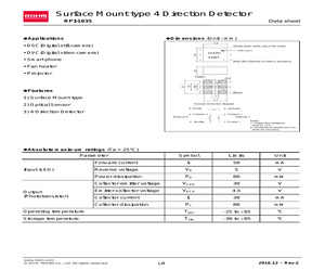
RPI-1035 Applications Dimensions (Unit : mm) * DSC(Digital still camera) * DVC(Digital video camera) * Smart phone * Fan heater * Projector Features 1) Surface Mount type 2) Optical Sensor 3) 4 Direction Detector Absolute maximum ratings (Ta = 25C) Symbol Limits Unit Forward current IF 50 mA Reverse voltage VR 5 V Power dissipation PD 80 mW Collector-emitter voltage VCEO 30 V Emitter-collector voltage VECO 4.5 V Collector current IC 30 mA Collector dissipation PC 80 mW Operating temperature Topr 25 to 85 C Storage temperature Tstg 30 to 85 C Parameter Input (LED) Output (Phototransistor) www.rohm.com (c) 2015 ROHM Co., Ltd. All rights reserved. 1/4 2016.12 - Rev.C Data Sheet RPI-1035 Electrical and optical characteristics (Ta = 25C) 1) Input characteristics Values Parameter Symbol Conditions Unit Min. Typ. Max. Forward voltage VF IF =50mA - 1.3 1.6 V Reverse current IR VR =5V - - 10 A 2) Output characteristics Values Parameter Symbol ICED Dark current Peak sensitivity wavelength Cond
 6 Pages, 348 KB, Original
RPI-1035 Applications Dimensions (Unit : mm) * DSC(Digital still camera) * DVC(Digital video camera) * Smart phone * Fan heater * Projector Features 1) Surface Mount type 2) Optical Sensor 3) 4 Direction Detector Absolute maximum ratings (Ta = 25C) Symbol Limits Unit Forward current IF 50 mA Reverse voltage VR 5 V Power dissipation PD 80 mW Collector-emitter voltage VCEO 30 V Emitter-collector voltage VECO 4.5 V Collector current IC 30 mA Collector dissipation PC 80 mW Operating temperature Topr 25 to 85 C Storage temperature Tstg 30 to 85 C Parameter Input (LED) Output (Phototransistor) www.rohm.com (c) 2015 ROHM Co., Ltd. All rights reserved. 1/4 2016.12 - Rev.C Data Sheet RPI-1035 Electrical and optical characteristics (Ta = 25C) 1) Input characteristics Values Parameter Symbol Conditions Unit Min. Typ. Max. Forward voltage VF IF =50mA - 1.3 1.6 V Reverse current IR VR =5V - - 10 A 2) Output characteristics Values Parameter Symbol ICED Dark current Peak sensitivity wavelength Cond
 5 Pages, 336 KB, Original
 upwards. Place shorter pins of the header into the appropriate soldering pads. 3 Turn the board upward again. Make sure to align the headers so that they are perpendicular to the board, then solder the pins carefully. 1. Introduction Tilt clickTM carries RPI-1035, a 4-directional optical tilt sensor. This type of sensor provides positional feedback for left, right, forward or backward movements. Tilt clickTM communicates with the target board microcontroller through mikroBUSTM PWM and INT lines, used here for Vout1 and Vout2 outputs from the sensor. In addition, two onboard LEDs provide visual feedback from the sensor. The board can use either a 3.3V or 5V power supply. 3. Plugging the board in Once you have soldered the headers your board is ready to be placed into the desired mikroBUSTM socket. Make sure to align the cut in the lower-right part of the board with the markings on the silkscreen at the mikroBUSTM socket. If all the pins are aligned correctly, push the board all the way into the s
 2 Pages, 895 KB, Original
 upwards. Place shorter pins of the header into the appropriate soldering pads. 3 Turn the board upward again. Make sure to align the headers so that they are perpendicular to the board, then solder the pins carefully. 1. Introduction Tilt clickTM carries RPI-1035, a 4-directional optical tilt sensor. This type of sensor provides positional feedback for left, right, forward or backward movements. Tilt clickTM communicates with the target board microcontroller through mikroBUSTM PWM and INT lines, used here for Vout1 and Vout2 outputs from the sensor. In addition, two onboard LEDs provide visual feedback from the sensor. The board can use either a 3.3V or 5V power supply. 3. Plugging the board in Once you have soldered the headers your board is ready to be placed into the desired mikroBUSTM socket. Make sure to align the cut in the lower-right part of the board with the markings on the silkscreen at the mikroBUSTM socket. If all the pins are aligned correctly, push the board all the way into the s
 3 Pages, 897 KB, Original


